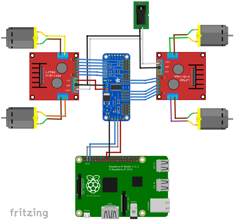

You would also be better to run off a single (possibly larger) battery. The pca9685 will run on 5V (5.5V is likely the maximum value, not operating!) so you don’t need the to step down switchers. I expect your leds will need a series current limiting resistor to set their operating current. It has 16 channels and that should do for 4 servos and 5 (or 10) leds. In this case as far as I can see a single pca9685 should do. Next, in battery power applications, you want to reduce both weight and current draw to maximize battery life. You need to know how much current the gear motors draw (it should be in their data sheet) to know what motor driver would be suitable for them. 2V drop in a DMOS output motor driver.) That wastes battery power.

The LM298 is transistor output and has about a 2V drop in the transistors (against perhaps. The first thing I would suggest is replace the motor driver. Please let me know if there are any enhancements that I could do Are all grounds are connected well in my circuit diagram How do I calculate how much current my circuit will require, I am okay with recharging batteries after ~40min of usageĤ. Do I have to connect other components registers capacitors for better current management if yes whereģ. Is one ESP 32 will enough for this or do I have to use 2 in I2CĢ. I am planning to control ESP32 via Bluetooth or my home WIFIġ. With 2 WAV audios (each being ~1 min long) stored in ESP32 as it has 4MB memoryħ. 1 Speaker 8 ohm and MAX98357A as audio amp module Control over WIFI/Bluetooth, by Android app(which I can develop from tutorials)Ħ. Hence I have decided to use gear reduction 100rpm or 300rpmĥ. Two 9V batteries (18V total) will be used with switch button on offĭc motors for wheels, it has to carry load of the whole circuit and robot body(~400gm), speed is not important Two DC motors 6v (Planning to use L298N as motor Driver )ĮSP32 will be powered by 5V pin of L298N and connected to Vin of ESP32

Two LM2596 step down from 9v to 5.5v for PCA9685Ĥ. There won't be any load on servos and will be off when reached at certain angleģ. 4 Stepper motor SG90 9gm ((Planning to use 2nd PCA9685 and 9V battery switch button) 10 Small LED RGB 5mm 5V (Planning to use PCA9685 and 9V battery switch button)Īll LEDs will be on all the time or some of them will be onĢ. Here my circuit Diagram ESP32 Connections.fzz (216.5 KB)ĮSP32 as main Controller 1. I know this is very ambitious project for beginner lik me but i couldnt help myself Have watched tutorials for each module I am using and combined them to make this circuit Hi Folks I am beginner to ESP 32 for my robot I am getting started with ESP32


 0 kommentar(er)
